Solutions
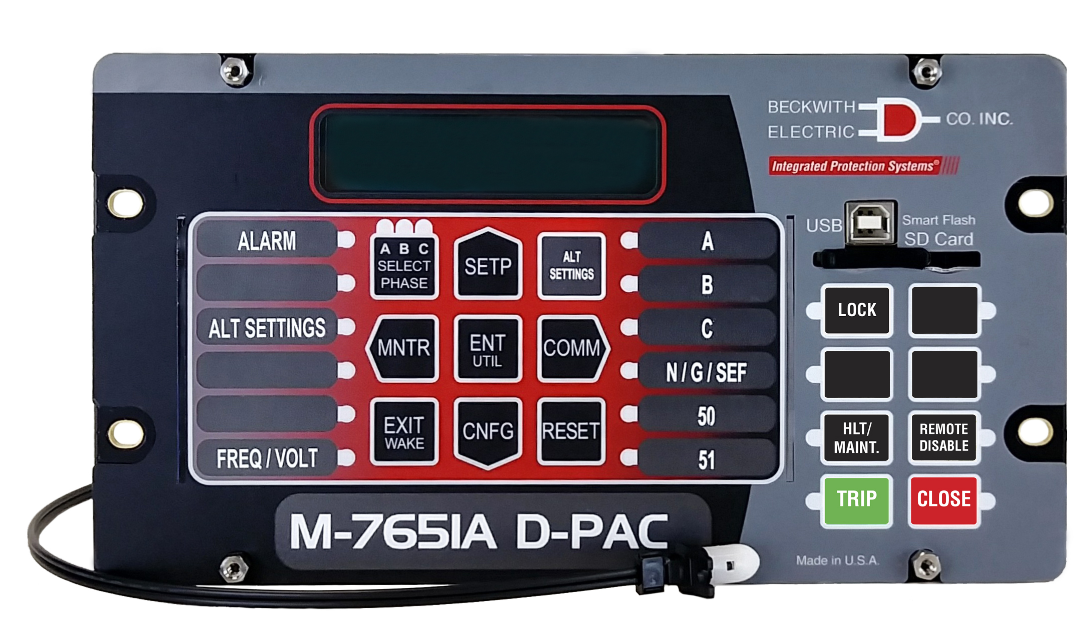
D-PAC Arc Flash Protection
 The Arc Flash Protection option detects arc flash conditions in switchgear and operates circuit breakers to remove the current source from the arc, thus mitigating the potential damage to equipment.
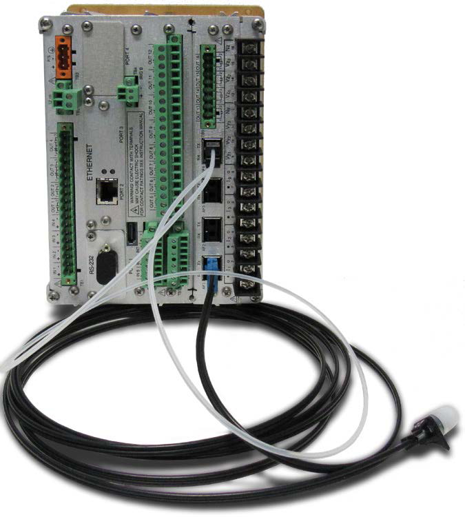
Four Optical Transceiver Ports interface to transparent fiber optic loops and/or point sensors. The output of the Optical Transceiver is compared to a pickup value. When the signal remains above the pickup for a predefined time delay, the relay will activate the dedicated high speed outputs. A current supervision function is also available to prevent false trips caused by other light sources not related to arcing. To monitor the integrity of the fiber optic links, the optical transceivers will transmit a light pulse every 2 seconds and verify the presence/absence of the pulse. The unit will generate an alarm when a failure is detected.
- Four Optical Transceiver Ports – Fiber Optic Loop and/or Point Sensor Ports incorporate self-test circuitry to provide continuous monitoring of the integrity of optical sensors, fiber cables, and the control unit to ensure reliable operation. If a failure is detected, the M‑7651A will generate an alarm to notify service personnel.
- Four High Speed Outputs – solid state output relays, with operating speed less than 4 ms.
Arc Flash Loop Sensor & Point Sensor Configuration Options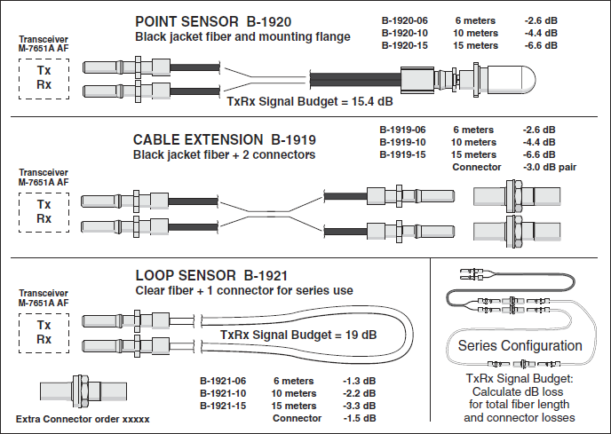
The sensor cable extension reach for each transceiver port is limited by the loss of optical signal strength in the fiber and each connector. Loop Sensors have the same loss rate as jacketed Cable Extensions at 0.22 dB per meter of fiber. Note that while a 15 meter Loop Sensor is actually 15 meters of fiber, a 15 meter Cable Extension introduces 30 meters of fiber signal loss. Each inline connector absorbs 1.5 dB of the signal so it is recommended that no more than four be used per transceiver port. The transceiver port Signal Budget is 19 dB for Loop Sensors and 15.4 dB for Point Sensors. These budgets include the loss of the plug into the transceiver, so loss calculations are simplified to Signal Budget minus the sum of fiber and connector losses.
In practical terms, the limit for extending a 15 meter Point Sensor is a 10 meter Cable Extension. The total of 50 meters of fiber plus two connectors results in the loss of 14 dB from the Signal Budget of 15.4 dB.
For a Loop Sensor installation with one Cable Extension of 15 meters, installing two 15 meter Loop Sensors with one connector in series is acceptable because the sum of signal loss equals 17.7 dB from the Signal Budget of 19 dB.
Maximum distance from the M-7651A can be reached using a 15 meter and a 10 meter Cable Extension with a 6 meter Loop Sensor. This configuration uses four connectors which are included with the Cable Extensions. The connector supplied with the Loop Sensor will not be needed.
Arc Flash Module Additional Communication Capabilities
The M‑7651A Arc Flash Module is capable of publishing any high speed output trip, in addition to Arc Flash detection events. It can also be configured to subscribe to any other manufacturer’s Arc Flash boolean GOOSE message. This may be used in the internal M‑7651A IPSlogic.