Protection & Control Seminar
Power Plant Protection Track
The Power Plant Protection Track would benefit those involved with protection of power plant assets in both utility, cogeneration, and heavy industrial environments, as well as those looking for a deeper background on the subject.
Sunday, July 28, 2024
5:00-7:00 PM
Seminar Check-in
- Please check-in for the seminar and pick-up your badge sometime between 5:00-7:00 PM on Sunday, July 28th.
- If you can't make it on Sunday, please stop by the Help Desk sometime between 7:00-8:00 AM on Monday, July 29th.
Monday, July 29, 2024
7:00-8:00 AM
Breakfast & Attendee Check-in
- Please check-in for the seminar and pick-up your badge at the Beckwith Electric Help Desk.
8:00-8:30 AM
Welcome & Introductions
8:30-9:45 AM
Generator Protection – IEEE C37.102
Generators are subject to internal faults, external faults and abnormal operating conditions impressed by turbine and excitation system issues, as well as power system events the generator has no control over but must cope with. False (nuisance) trips are costly as the generator’s output is lost. Inability to trip due to lack of sensitivity, lack of certain protections or deficiencies in protection application may cause severe damage to generators, resulting in prolonged outage and revenue loss, plus increased system stability risk. Achieving the ideal balance of secure and dependable protection involves use of an array of elements that protect the generator for all operating modes: off-line, start up, synchronizing, various levels of power output and when challenged by system faults and anomalies.
- Generator construction and operation
- Grounding and connections
- IEEE standards for generator protection
- IEEE C37.102 (Guide for AC Generator Protection)
- Generator and power system interaction
- Generator protection element overview
- Internal faults (in the generator zone)
- Abnormal operating conditions
- External faults
- Protection Application Exploration
- Stator Ground Fault (27TN, 59N, 59D, 64S, 67N, 87GD)
- Exploration of stator ground fault injection protection sensitivity and security
- Rotor Ground Fault/Brush Lift Off (64F, 64B)
- Stator Phase Fault (87G)
- Turn-to-Turn Fault
- Phase Unbalance/Open Conductor (46)
- Overexcitation (24)
- Abnormal Voltage (59)
- Phase Fault Backup (21)
- Field Loss (40)
- Loss of Synchronism (78)
- Abnormal Frequency (81-U, 81A)
- Inadvertent Energizing (50/27)
- Blown VT Fuses (60FL)
- Breaker Failure/Pole Flashover (50BF)
- Loss of Prime Mover (32)
- Stator Ground Fault (27TN, 59N, 59D, 64S, 67N, 87GD)
- Tripping considerations and sequential tripping
- Discuss tactics to improve reliability (security & dependability)
- Generator protection upgrade considerations
- Redundancy concepts
- Explore Setting, Commissioning and Event Investigation Tools
9:45-10:00 AM
Break
10:00 AM-Noon
Generator Protection – IEEE C37.102 (Continued)
Noon-1:00 PM
Lunch
1:00-2:45 PM
Generator Protection – IEEE C37.102 (Continued)
2:45-3:00 PM
Break
3:00-4:00 PM
Fault Fundamentals
- Fault Types
- Short-Circuit Calculations
- Calculations and Settings
4:00-5:00 PM
Power Quality for Industrial Applications
Maintaining high power quality is essential to energy efficiency and energy cost management, as well as customer satisfaction. Low power quality can damage equipment, cause data loss or corruption, and result in costly power outages. International standards such as IEC 61000-4-30 establish power quality parameters that must be adhered to and processes for measuring the parameters. Meters that are certified to the IEC 61000-4-30 standard have demonstrated their ability to accurately measure the standard’s power quality parameters. Power quality meters must also provide alarm/limit capabilities and waveform recording for after event analysis. EN 50160 reporting is an important feature for meters sold in the European market. It gives the main characteristics of the grid voltage at the customer’s supply terminal under normal operating conditions.
- IEC 61000-4-30 standard implementation
- Power quality classes – S and A
- Power quality testing and measurement techniques
- Power frequency
- Voltage magnitude
- Flicker
- Supply voltage dips and swells
- Voltage interruptions
- Transients, voltage harmonics, and interharmonics
- Voltage unbalance
- Mains signaling voltage on the supply mains
- Rapid voltage changes
- Underdeviation and overdeviation parameters
- Limits/alarms
- Power quality limits
- Alarm emails
- I/O communication for control applications
- EN 50160 reporting
Monday Evening Activities
5:30-9:45 PM
Dinner Cruise
On Monday evening, July 29th, join us for a dinner cruise! This will include a full, restaurant-style menu featuring continental cuisine prepared fresh on board.
- Meet at 5:30 PM in front of the Bird Key (Distribution Track Classroom) at the TradeWinds for bus transportation.
- The cruise departs at 6:30 PM and returns at 9:30 PM. The bus returns to TradeWinds by 9:45 PM.
- RSVP is required to attend. To attend the cruise, RSVP must be received by Tuesday, July 16.
- The cruise is limited to registered attendees and guests that have a Companion Guest Pass.


Tuesday, July 30, 2024
7:00-8:00 AM
Breakfast
8:00-9:45 AM
Generator Protection Calculations & Settings
- Building on the base knowledge covered in Generator Protection Fundamentals, calculations for protective elements are developed.
- Depending on the element, these calculations use nameplate data, system data or a combination of the two.
- Margin considerations are explored and impacts on element reliability are discussed, as well as element interdependencies with protection and control in the generator zone, local power plant and system.
9:45-10:00 AM
Break
10:00 AM-Noon
Generator Protection Calculations & Settings (Continued)
Noon-1:00 PM
Lunch
1:00-2:45 PM
Generator Protection Calculations & Settings (Continued)
2:45-3:00 PM
Break
3:00-4:30 PM
Generator Protection Calculations & Settings (Continued)
Tuesday Evening Activities
6:00-9:00 PM
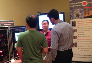
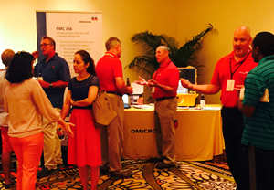
Hospitality & Demo Expo
- Please join us Tuesday evening from 6:00-9:00 PM for the Networking & Demo Expo.
- Beckwith Electric and Special Guests will host a reception for a time of networking and information sharing including food and drinks.
Wednesday, July 31, 2024
7:00-8:00 AM
Breakfast
8:00-9:00 AM
LTC Transformer Paralleling
9:00-9:45 AM
Transformer Protection – IEEE C37.91
Transformers are subject to internal faults, the effects of external faults and abnormal operating conditions impressed by the power system events the transformer has no control over but must cope with. False (nuisance) trips are costly as the transformer and load are disconnected. Inability to trip due to lack of sensitivity, lack of certain protections or deficiencies in protection application may cause severe damage to transformers, negatively impacting power flows, impacting power quality and compromising stability. Achieving the ideal balance of secure and dependable protection involves use of an array of elements that protect the transformer from prolonged internal faults, excessive through faults and when challenged by power system faults and anomalies.
- Why transformers fail
- The cost of failures
- IEEE C37.91 (Guide for Protecting Power Transformers)
- IEEE Devices used in Transformer Protection
- Transformer Protection Review
- Transformer Protection Functions
- Explore Protection Functions
- 87T Phase Differential Characteristic
- Compensation in Digital Relays
- Relay Configuration: Winding Arrangement and CT Connection
- 87T Phase Differential Characteristic
- Overcurrent based (50, 51, 50N, 51N, 46)
- Through fault protection (TFM)
- Current Summing & Through-Fault
- Overexcitation (24)
- Generating plant causes
- T&D system causes
- Protection Against Overexcitation – V/Hz versus 5th Harmonic
- Phase Differential (87T)
- Unique Issues Applying to Transformer Differential Protection
- CT performance issues (saturation, remnant flux, tolerance, rating)
- Percentage differential characteristics with variable percentage slopes
- Internal ground fault sensitivity
- Restraints for inrush and overexcitation
- Overexcitation 87T Blocking Restraint – Failure to detect nascent fault
- Overexcitation Adaptive 87T Pickup Restraint – Detects nascent faults
- Adaptive restraint for security
- Point-on-Wave Switching Inrush
- Cross Phase Averaging
- Switch-onto-Fault
- Unique Issues Applying to Transformer Differential Protection
- High Set Phase Differential (87H)
- Ground Differential (87GD), Restricted Earth Fault (REF)
- Interface and Analysis Software: Desirable Attributes
- NERC “State of Reliability”
- Elegant Simplicity – Realization of configuration, settings, logic, monitoring
9:45-10:00 AM
Break
10:00 AM-Noon
Transformer Protection – IEEE C37.91 (Continued)
Noon-1:00 PM
Lunch
1:00-2:45 PM
Advanced Transformer Protection
2:45-3:00 PM
Break
3:00-4:00 PM
Transformer Protection Calculations & Settings – Differential Elements
Building on the base knowledge covered in Transformer Protection Fundamentals, calculations for protective elements are developed. Depending on the element, these calculations use nameplate data, system data or a combination of the two. Margin considerations are explored and impacts on element reliability are discussed, as well as element interdependencies with protection and control in the transformer zone, whether in generation, transmission or distribution.
4:00-5:30 PM
Event Analysis Case Studies
Thursday, August 1, 2024
8:00-9:45 PM
Motor Bus Transfer
Motor Bus Transfer is the process of rapidly transferring sources to a motor bus for planned source switching and unplanned source failure. The rapid transfer allows the process to continue without interruption. To avoid damage to the motors, specialized equipment and methods are employed to cope with the dynamics of motor deceleration, and voltage and phase angle change between the new source and the motor bus. Improper reconnection of the motor bus can cause cumulative or immediate damage to the motors, and result in a process crash.
- Residual Voltage Transfers always thought to be safe even if completed out-of-phase, can cause significant torques on motors, exceeding a 3-phase fault at the motor terminals.
- IEEE C37.96 identifies events that occur or conditions that exist prior to and during transfer where, at transfer initiate, the initial phase angle may be nowhere near zero!
- So at the end of a Residual Voltage Transfer spin down, the close phase angle may be nowhere near zero!
- Research with modeling motors during transfer has proven that in 40% of the cases closing at varied angles, the peak-to-peak torques developed during the Residual Voltage Transfer are higher than the 3-Phase Short Circuit Torques of the motors on the bus.
- This research has revealed that the peak currents in motors during Residual Voltage Transfers are higher than the 3-Phase Short Circuit Currents in more than 60% of these cases.
- This motor modeling research also shows that in 89% of the cases closing at varied angles, the currents during Residual Voltage Transfer are in excess of six times rated current.
- Synchronous In-Phase Transfers may take longer than some arbitrary time limit. Depending on the initial phase angle at transfer initiate, it may take more than 6 or 10 cycles for the motors to rotate back into synchronism.
- Compared to blind Residual Voltage Transfers, these Synchronous In-Phase Transfers are much faster, closing at much higher voltages, at much lower slip frequencies, with closure near zero degrees and low inrush current and torque.
- The 1.33 resultant pu V/Hz transfer criterion in NEMA MG-1, ANSI/NEMA C50.41 and IEEE C37.96 has no correlation to motor torque and actually gives passing grades to severely excessive torques upon transfer.
- Time period transfer criteria, stated in NEMA MG-1, IEEE 666, ANSI/NEMA C50.41 and IEEE C37.96, are arbitrary and would permit severely out-of-phase transfers or conversely may preclude perfectly good synchronous transfers.
- A Motor Torque Ratio TPK /TL, introduced as the aggregate peak torque at transfer expressed as a multiple of the aggregate load torque prior to transfer, displays a high correlation to the phase angle at transfer with little effect from voltage or frequency difference.
- If it is torque that reduces the life expectancy and damages motors or driven equipment, or both, as suggested in the C50.41 Standard, then the industry must use a torque-based criterion to assess if transfers are being completed within acceptable torque limits.
Course Outline:
- Introduction
- Why Transfer Motor Load Sources
- Basic Application Configurations
- Primary-Backup
- Main-Tie-Main
- Multiple-Option Source Selection
- IEEE Std C37.96-2012 Motor Bus Transfer Classification – Methods & Modes
- Automatic and Manual
- Closed Transition Method – Hot Parallel Transfer
- Open Transition Method – Fast, In-Phase, Residual Voltage
- Open Transition Modes – Simultaneous, Sequential
- IEEE Std C37.96-2012 Conditions Across Normally Open Startup or Bus Tie Breaker – Before / During Transfer
- Effects of a Fault
- Out-of-Step (OOS) Generator Trip
- System Separation between Incoming Supply Sources
- Supply Source Transformer Winding Phase Shift
- Transient Effects upon Disconnect of Motor Loads
- Motor and Load Characteristic Effects on MBT
- Failed Residual Voltage Transfer – Case Study
- Transfer Initiate, Inadvertent External Operation, Lockouts
- Load Shed During Transfer
- ANSI/NEMA Standard C50.41-2012
- Resultant per unit V/Hz Limits
- Bus Transfer Spin Down Testing, Acceptance Testing, Setting Considerations
- Spin Down Analysis & Settings Calculations – Case Study
- Sequential vs. Simultaneous Transfer, The Need for Speed – Case Study
- IEEE Fast Transfer Sync Check Relay Performance Test Protocol Results
- IEEE Residual Voltage Transfer Relay Performance Test Protocol Results
- Motor Bus Transfer System Dynamic Performance Test Protocol Results and Observations
- A Motor Bus Transfer Torque Ratio Criterion applied to Live Open Transition Transfers Under Normal Operating Load Conditions
- Observations and Conclusions
- Test Results from Modeling of Transient Currents and Torques on Motors during Residual Voltage Motor Bus Transfer
- Conclusions
9:45-10:00 AM
Break
Noon-1:00 PM
Lunch
Thursday Beckwith Factory Tour
3:30-6:00 PM
Beckwith Electric Factory Tour
Visit the Beckwith Electric factory for a behind-the-scenes look at our advanced manufacturing and services capabilities at work. Discover how we turn raw material into cutting-edge technology. Experience the Beckwith Electric commitment to quality, equipment reliability, testing procedures, new product development, and customer service. Talk to Beckwith Electric technical and product support staff and learn first-hand about our technology through live product demonstrations.
Includes transportation to and from the seminar venue.
- 3:30 PM
- Load Shuttle Bus at TradeWinds Resort for Beckwith Headquarters
- 3:30-4:00 PM
- Travel to Beckwith
- 4:00-5:30 PM
- Beckwith Electric Factory Tour & Product Demo
- 5:30 PM
- Load Shuttle Bus at Beckwith to return to TradeWinds Resort
- 5:30-6:00 PM
- Travel to TradeWinds Resort
Generation Protection Hands-on Testing Lab Breakout Session
Register early as seats will be limited for Breakout Session!
Thursday, August 1, 2024
10:00 AM-Noon
Protection and control systems play a key role for the safe and reliable operation of today’s electricity power systems. The complexity of multifunction digital protection presents considerable challenges to those responsible for testing and commissioning these devices. These hands-on sessions are designed for individuals who are not required to learn complex setting equations, but want a solid understanding of proper test procedures.
The following will be included in the Hands-on Testing Lab Breakout Sessions:
- Learn skills required to test and commission Beckwith relays.
- Gain familiarity with the operating principles of Beckwith relays and controls.
- Hands-on experience with Beckwith IPSCom to assist in the testing process.
Transformer Protection Hands-on Testing Lab Breakout Session
Register early as seats will be limited for Breakout Session!
Thursday, August 1, 2024
1:00-3:00 PM
Protection and control systems play a key role for the safe and reliable operation of today’s electricity power systems. The complexity of multifunction digital protection presents considerable challenges to those responsible for testing and commissioning these devices. These hands-on sessions are designed for individuals who are not required to learn complex setting equations, but want a solid understanding of proper test procedures.
The following will be included in the Hands-on Testing Lab Breakout Sessions:
- Learn skills required to test and commission Beckwith relays.
- Gain familiarity with the operating principles of Beckwith relays and controls.
- Hands-on experience with Beckwith IPSCom to assist in the testing process.